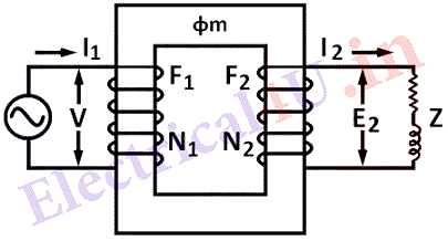
A transformer may be defined as a static electrical apparatus(electromagnetic device) consist of two or more windings which link with a common magnetic field. Transformers converts electrical energy from higher voltage to lower voltage or vice versa through a medium of electric flux, i.e. it transfers electrical energy from one circuit to another. Fig. (a) shows a simple representation of a single-phase transformer. They are widely used in the power system. The use of transformers makes it possible to generate at most economical voltage, transmit power at economical transmission voltage and utilize power at most economical and effective voltage for the particular utilization devices.

It consists mainly of magnetic core on which two windings are wound, primary and secondary. The primary is supplied with an A.C. source of supply, of voltage V volts and frequency f cycles per second. The current flowing in the primary winding produces time varying flux. This flux links with both the windings and produces induced e.m.f. The e.m.f. induced in the primary is equal and opposite to the applied voltage neglecting losses. The e. m. f. is also produced in the secondary winding due to this mutual flux. This depends on the ratio of number of turns in the primary and the secondary winding of the transformer.
E. M. F. EQUATION:
Let N1 and N2 be the number of turns of the primary and secondary winding. Let Φ be the flux produced due to current (excitation current) passing through the primary when connected to an A.C. supply. The current produces the flux which may be considered in phase. Let the flux then vary sinusoidally with time as does the current.
\phi=\phi_{\max } \sin \omega t where \phi max is the maximum value of flux in Weber’s and \omega=2 \pi f t. Where f is frequency in c/s. The instantaneous value of the e.m.f. induced in the primary
e_{1}=-\frac{d \phi}{d t} \times \mathcal{N}_{1} \text { volts } \cdots \text { by } \text { Faraday's Law }
=-\phi_{\max } \omega \cos \omega t \times \mathcal{N}{1}=-2 \pi f \phi{\max } \mathcal{N}_{1} \cos \omega t
Therefore maximum e.m.f. E_{1 m a x}=-2 \pi \phi_{m a x} f \mathcal{N}_{1} and its r.m.s. or effective value is given by:-
E_{1}=-\frac{2 \pi}{\sqrt{2}} \phi_{\max } f \mathcal{N}{1}=4 \cdot 44 \phi{\max } f \mathcal{N}_{1} \text { volts }
The polarity of the induced e.m.f. is given by Lenz’s law., and it opposes the flux change.
