In ideal transformer, the following assumptions are made:
(i) The winding resistances are negligible.
(ii) All the flux produced is confined to the core of the transformer and links fully both the windings. There is no leakage of flux.
(iii) Permeability of core is high so that the magnetizing current required to establish flux is negligible.
(iv) Hysteresis and eddy current losses are absent or are negligible.
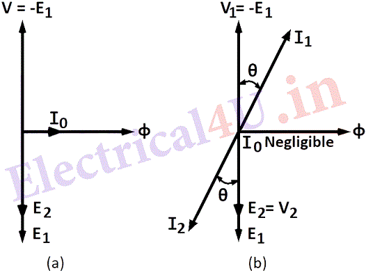
It is proved in the last section, that the e. m. f. induced in primary winding is E_{1}=4 \cdot 44 \phi_{\max } f \mathcal{N}_{1} volts. It is seen that when instantaneous current and flux is a sine function, e is minus cosine function and lags behind the flux by 90°. The applied voltage V should be equal and opposite to E1. Fig.(a) shows the phasor diagram for ideal transformer on no load.
The secondary winding having N2 turns links with the same flux Φ and so the e.m.f. induced in it E2 is given by
E_{2}=-4 \cdot 44 \phi_{\max } f \mathcal{N}_{2} \text { volts }...(eq 1)
(a) on no load (b) on load
Therefore, the ratio of the voltages induced in primary to secondary
\frac{E_{1}}{E_{2}}=\frac{\mathcal{N}{1}}{\mathcal{N}{2}} ...(eq 2)If the voltage across the primary is V1 and across the secondary V2 volts, assuming ideal conditions
V_{1}=E_{1} \text { and } V_{2}=E_{2} \text { and } \frac{V_{1}}{V_{2}}=\frac{\mathcal{N_{1}}}{N_{2}}
CURRENT RATIOS:
Let an impedance Z2 be connected across the secondary terminals. Then current in the secondary I_{2}=\frac{V_{2}}{Z_{2}}. This current in the secondary will produce an m.m.f. F_{2}=N_{2}I_{2}
This secondary m.m.f. is in opposition to the core flux and radically changes the core flux affecting voltage conditions unless it is compensated by equal m.m.f. from the primary side.
F_{1}=I_{1} \mathcal{N}_{1}=F_{2}=I_{2} \mathcal{N}_{2} ...(eq 3)
Therefore, \frac{I_{1}}{I_{2}}=\frac{\mathcal{N_{2}}}{N_{1}}
Fig. (b) shows the phasor diagram of an ideal transformer on load with a lagging power factor of cos θ. Here it will be seen that I1 lags behind V1 by an angle θ, as I2 lags behind V2 by an angle θ. This is neglecting the no load current.
A transformer can act as a step up or step-down transformer i.e., can increase or decrease the voltage from one side to the other side. So primary and secondary are relative terms depending on which is the input side and which is the output side. It is therefore more correct to consider the windings of a transformer as high voltage and low voltage sides instead of primary and secondary.
EQUIVALENT IMPEDANCE:
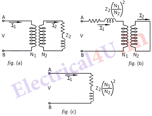
When impedance Z2 is connected as load in the secondary circuit of the transformer, its effect in the primary circuit can be seen by considering the voltage and current ratio expression.
\frac{V_{1}}{V_{2}}=\frac{\mathcal{N_{1}}}{\mathcal{N_{2}}} ; \quad \frac{I_{1}}{I_{2}}=\frac{\mathcal{N_{2}}}{\mathcal{N_{1}}}
\text { Therefore } \frac{V_{1}}{I_{1}}=\left(\frac{\mathcal{N}{1}}{\mathcal{N}{2}}\right)^{2} \frac{V_{2}}{I_{2}}
\text { or } \quad Z_{1}=\left(\frac{\mathcal{N_{1}}}{\mathcal{N_{2}}}\right)^{2} z_{2}
Following fig. shows equivalent circuit.

When impedance Z1 of above value is considered in primary side, it is equivalent of replacing the impedance Z2 in the secondary side and the performance of the transformer as viewed from the terminals A B remains the same. Transferring the impedance from one side of the transformer to the other side in this way is called referring the impedance to the other side. In the same way, the voltages and currents can also be considered referred to any one side using the voltage and current relations. Thus in ideal transfer:
(i) Voltages on each side are directly proportional to the number of turns.
(ii) Currents on each side are inversely proportional to the number of turns.
(iii) impedances (resistance and reactance individually) on each side are directly proportional to the square of the ratio of number of turns.
(iv) Power and volt amperes are unchanged and remain the same.
